
Page 22 - Inorganic Mass Spectrometry - Fundamentals and Applications
P. 22
12 Smit~
1001 NlST U-100
Mass (Daltons)
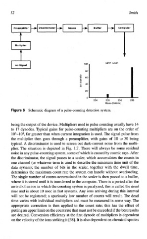
Fi~~re Schematic diagram of a pulse-counting detection system.
6
being the output of the device. ~ultipliers used in pulse counting usually have 14
to 17 dynodes. Typical gains for pulse-counting multipliers are on the order of
106--108, far greater than when current integration is used. The signal pulse from
the multiplier then goes through a preamplifier, with gains of 10 to 30 being
typical. A discriminator is used to screen out dark-current noise from the multi-
plier. The situation is depicted in Fig. 1.7. There will always be some residual
noise in any pulse-counting system, some of which is caused by cosmic rays. After
the disc~minator, the signal passes to a scaler, which accumulates the counts in
one channel (or whatever term is used to describe the minimum time unit of the
data system); the number of bits in the scaler, together with the dwell time,
dete~nes the maximum count rate the system can handle without overloading.
The single number of counts accumulated in the scaler is then passed to a buffer,
where it is stored until it is transferred to the computer. "here is a period after the
arrival of an ion in which the counting system is paralyzed; this is called the dead
time and is about 10 nsec in fast systems. Any ions arriving during this interval
will not be registered; a spuriously low number of counts will result. The dead
time varies with individual multipliers and must be measured in some way. The
appropriate correction is then applied to the count rate; this has the effect of
putting an upper limit on the count rate that must not be exceeded if the best results
are desired. Conversion efficiency at the first dynode of multipliers is dependent
on the velocity of the ions striking it [38]. It is also dependent on chemical species