
Page 58 - Inorganic Mass Spectrometry : Fundamentals and Applications
P. 58
48 ~ars~i~k
the greater mobility of the electrons (compared to that of positive ions), the surface
potential decays toward zero faster than in the previous half-cycle; the resulting
potential on the surface is 0.5 kV As the second full cycle is initiated and the
polarity of the electrode is switched, the resulting potential is - 1.5 kV. After
several cycles, the waveform of V, reaches a constant negative dc offset; this is the
self-bias ~otentia2. The dc offset is approximately one half the applied peak-to-
peak voltage. The exact value depends on the discharge pressure and source
geometry. The sample surface is alternatively bombarded by high-energy ions and
low-energy electrons but for most purposes can be considered a continuous dc
discharge with a superimposed ac potential.
Pin and Planar Cathode Discharge Geometries
Pin cathodes (such as that shown in Fig. 2.7) and planar cathodes (such as that
shown in Fig. 2.8) are the two discharge geometries used most extensively in
S. This pattern is due primarily to the simplicity of their const~ction and
operation, and the relative ease of sample interchange. Typical operating condi-
tions for the pin cathode include pressures that range from 0.5 to 5 torr of a rare
gas, voltages of between 500 and 3000 V, and currents of between 0.5 and 5 d.
The sample is usually a cylindrical rod, 1-3 m in diameter, with 5- 15 m of
length exposed to the discharge. Because of their convenient sample geometry,
trace
pin cathodes have found widespread use in elemental analysis of bulk solids.
to
a
A planar cathode operates under similar pressure and voltage conditions
coaxial cathode. To maintain. comparable current densities, however, these
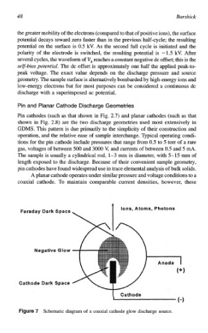
Ions, Atoms, Photons
7 Schematic diagram of a coaxial cathode glow discharge source.