
Page 65 - Solutions Manual to accompany Electric Machinery Fundamentals
P. 65
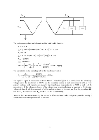
I I
L,P L,S
+
V LL,P V LL,S Load 1 Load 2
-
The loads on each phase are balanced, and the total load is found as:
P 200 kW
1
Q 1 P 1 tan 200 kW tan cos -1 0.85 124 kvar
P 60 kW
2
Q 2 P 2 tan 60 kW tan cos -1 0.9 29 kvar
P TOT 260 kW
Q TOT 153 kvar
Q 153 kvar
PF cos tan 1 TOT cos tan 1 0.862 lagging
P TOT 260 kW
The line current on the secondary side of the transformer bank is
P 260 kW
I LS TOT 363 A
3 V LS PF 3 480 V 0.862
The open-Y—open connection is shown below. From the figure, it is obvious that the secondary
voltage across the transformer is 480 V, and the secondary current in each transformer is 246 A. The
primary voltages and currents are given by the transformer turns ratios to be 7967 V and 14.8 A,
respectively. If the voltage of phase A of the primary side is arbitrarily taken as an angle of 0°, then the
voltage of phase B will be at an angle of –120°, and the voltages of phases A and B on the secondary side
will be V AS 480 0 V and V BS 480 120 V respectively.
Note that line currents are shifted by 30 due to the difference between line and phase quantities, and by a
further 30.5 due to the power factor of the load.
59