
Page 321 - Intelligent Digital Oil And Gas Fields
P. 321
266 Intelligent Digital Oil and Gas Fields
shows the IPR curves for individual zone and the combined IPR for
commingled unrestricted production. If the operating objective is to main-
tain constant flow at Zones 1, 3, and 4, and to restrict flow in Zone 2% to 40%
of unconstrained flow, then the flowing bottom-hole pressure must be
restored to the original pressure. Controlling the valve in Zone 2, the atten-
uated IPR curve for Zone 2, with a flow control valve setting of 40%,
is shown in Fig. 7.12, along with the unrestricted IPR curves of the
other zones.
7.6.3 Coupling Wellbore and Gridded Simulators to Model ICVs
Wells with ICVs can be modeled using commercial well performance soft-
ware coupled with a 3D numerical model. The numerical model simulators
use a finite difference three-phase simulator, which has been described
widely (Coats et al., 2004; Shiralkar et al., 2005). The simulator has a
gridded-cell wellbore and network tubular models that are connected to
“wellnodes” and linked by “connection.” Valve connections are between
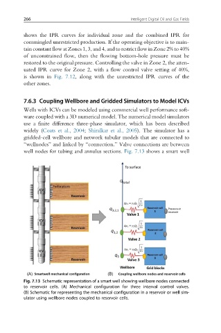
well nodes for tubing and annulus sections. Fig. 7.13 shows a smart well
Fig. 7.13 Schematic representation of a smart well showing wellbore nodes connected
to reservoir cells. (A) Mechanical configuration for three interval control valves.
(B) Schematic for representing the mechanical configuration in a reservoir or well sim-
ulator using wellbore nodes coupled to reservoir cells.