
Page 271 - Intro Predictive Maintenance
P. 271
262 An Introduction to Predictive Maintenance
Figure 12–1 “Go/no-go” standards.
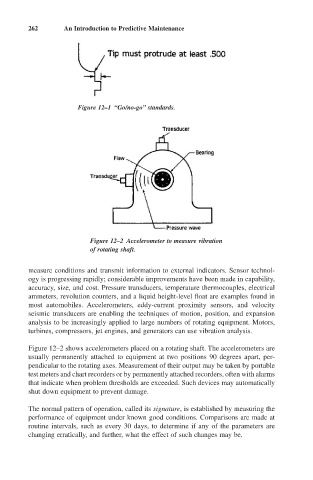
Figure 12–2 Accelerometer to measure vibration
of rotating shaft.
measure conditions and transmit information to external indicators. Sensor technol-
ogy is progressing rapidly; considerable improvements have been made in capability,
accuracy, size, and cost. Pressure transducers, temperature thermocouples, electrical
ammeters, revolution counters, and a liquid height-level float are examples found in
most automobiles. Accelerometers, eddy-current proximity sensors, and velocity
seismic transducers are enabling the techniques of motion, position, and expansion
analysis to be increasingly applied to large numbers of rotating equipment. Motors,
turbines, compressors, jet engines, and generators can use vibration analysis.
Figure 12–2 shows accelerometers placed on a rotating shaft. The accelerometers are
usually permanently attached to equipment at two positions 90 degrees apart, per-
pendicular to the rotating axes. Measurement of their output may be taken by portable
test meters and chart recorders or by permanently attached recorders, often with alarms
that indicate when problem thresholds are exceeded. Such devices may automatically
shut down equipment to prevent damage.
The normal pattern of operation, called its signature, is established by measuring the
performance of equipment under known good conditions. Comparisons are made at
routine intervals, such as every 30 days, to determine if any of the parameters are
changing erratically, and further, what the effect of such changes may be.