
Page 84 - Intro Predictive Maintenance
P. 84
Machine-Train Monitoring Parameters 75
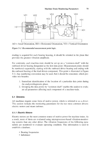
AO = Axial Orientation, HO = Horizontal Orientation, VO = Vertical Orientation
Figure 5–1 Recommended measurement point logic.
reading is acquired for each bearing housing, it should be oriented in the plane that
provides the greatest vibration amplitude.
For continuity, each machine-train should be set up on a “common-shaft” with the
outboard driver bearing designated as the first data point. Measurement points should
be numbered sequentially, starting with the outboard driver bearing and ending with
the outboard bearing of the final driven component. This point is illustrated in Figure
5–1. Any numbering convention may be used, but it should be consistent, which pro-
vides two benefits:
1. Immediate identification of the location of a particular data point during
the analysis/diagnostic phase.
2. Grouping the data points by “common shaft” enables the analyst to evalu-
ate all parameters affecting each component of a machine-train.
5.1 DRIVERS
All machines require some form of motive power, which is referred to as a driver.
This section includes the monitoring parameters for the two most common drivers:
electric motors and steam turbines.
5.1.1 Electric Motors
Electric motors are the most common source of motive power for machine-trains. As
a result, more of them are evaluated using microprocessor-based vibration-monitor-
ing systems than any other driver. The vibration frequencies of the following para-
meters are monitored to evaluate operating condition. This information is used to
establish a database.
• Bearing frequencies
• Imbalance