
Page 184 - Intro to Space Sciences Spacecraft Applications
P. 184
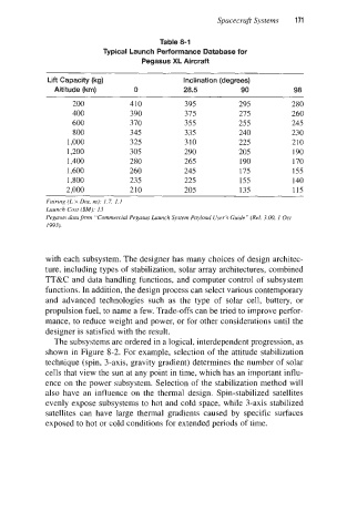
Table 8-1      Spacecraft Systems   171
                                   Typical Launch Performance Database for
                                             Pegasus XL Aircraft

                     Lift Capacity (kg)                Inclination (degrees)
                       Altitude (km)       0           28.5           90           98

                           200            410          395           295          280
                           400            390          375           275          260
                           600            370          355           255          245
                           800            345          335           240          230
                          1,000           325          310           225          210
                          1,200           305          290           205          190
                          1,400           280          265           190          170
                          1,600           260          245           175          155
                          1,800           235          225           155          140
                          2,000           210          205           135           115
                     Fairing (L x Diu, m): 1.7, 1.1
                     Launch Cost ($M):
                                  13
                     Pegasus data from “Commercial Pegasus Launch System Payload User’s Guide” (Rel. 3.00, I  Oct
                     I993 ).


                     with each subsystem. The designer has many choices of design architec-
                     ture, including types of  stabilization, solar array architectures, combined
                     TT&C and data handling functions, and computer control of  subsystem
                     functions. In addition, the design process can select various contemporary
                     and  advanced  technologies  such  as  the  type  of  solar  cell,  battery,  or
                     propulsion fuel, to name a few. Trade-offs can be tried to improve perfor-
                     mance, to reduce weight and power, or for other considerations until the
                     designer is satisfied with the result.
                       The subsystems are ordered in a logical, interdependent progression, as
                     shown in Figure 8-2. For example, selection of the attitude stabilization
                     technique (spin, 3-axis, gravity gradient) determines the number of  solar
                     cells that view the sun at any point in time, which has an important influ-
                     ence on the power subsystem. Selection of the stabilization method will
                     also have an  influence on the  thermal design. Spin-stabilized satellites
                     evenly expose subsystems to hot and cold space, while 3-axis stabilized
                     satellites can  have  large thermal  gradients caused by  specific surfaces
                     exposed to hot or cold conditions for extended periods of time.