
Page 467 - Introduction to Information Optics
P. 467
452 8. Information Storage with Optics
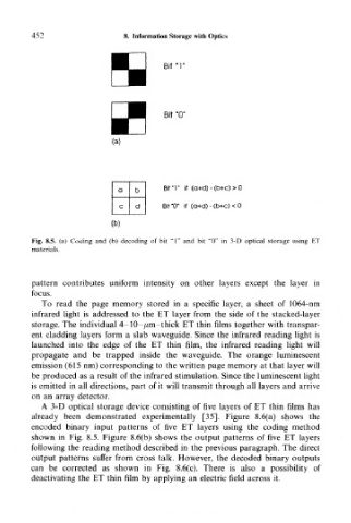
H Birr
Bit "0"
(a)
a b BitT if (a+d) - (b+c) > 0
c d Bit "0" if (a+d) - (b+c) < 0
(b)
Fig. 8.5. (a) Coding and (b) decoding of bit "1" and bit "0" in 3-D optical storage using ET
materials.
pattern contributes uniform intensity on other layers except the layer in
focus.
To read the page memory stored in a specific layer, a sheet of 1064-nm
infrared light is addressed to the ET layer from the side of the stacked-layer
storage. The individual 4-10-/mi-thick ET thin films together with transpar-
ent cladding layers form a slab waveguide. Since the infrared reading light is
launched into the edge of the ET thin film, the infrared reading light will
propagate and be trapped inside the waveguide. The orange luminescent
emission (615 nm) corresponding to the written page memory at that layer will
be produced as a result of the infrared stimulation. Since the luminescent light
is emitted in all directions, part of it will transmit through all layers and arrive
on an array detector.
A 3-D optical storage device consisting of five layers of ET thin films has
already been demonstrated experimentally [35]. Figure 8.6(a) shows the
encoded binary input patterns of five ET layers using the coding method
shown in Fig. 8.5. Figure 8.6(b) shows the output patterns of five ET layers
following the reading method described in the previous paragraph. The direct
output patterns suffer from cross talk. However, the decoded binary outputs
can be corrected as shown in Fig. 8.6(c). There is also a possibility of
deactivating the ET thin film by applying an electric field across it.