
Page 726 - Introduction to Information Optics
P. 726
710 12. Networking with Optics
2n wavelengths (n passing clockwise through the ring, n passing counterclock-
wise). At CPE, an OADM picks up two of the 2n wavelengths on the
ring — one traveling clockwise, one counterclockwise. The two wavelengths
enter a switch. One of the wavelengths is converted directly to bandwidth for
use by the building's tenants, at 100 Mb/s per tenant. The other provides an
alternate route in case the first link fails due to a break in the fiber or a failure
in one of the network devices. If fiber is cut on the way into the building, for
instance, the switch will sense that packets are not coming through its primary
port. It automatically will shift to the secondary port. Likewise, if a device fails
on the customer network, the Internet connection is still guaranteed. This type
of DWDM/router-based network is preferred by emerging Internet service
providers that are looking to deliver more bandwidth at lower cost to their end
users. As voice- and video-over IP matures, this network promises to deliver
all services to the end user via an optical IP infrastructure.
SONET- based metro networks focus on providing data intelligence using
a voice-optimized SONET platform. The SONET multiservice provisioning
platform (MSPP) and passive optical network (PON) [28] are the two most
active areas at present. SONET MSPPs use full or slimmed-down versions of
SONET with added statistical multiplexing to handle other non- SONET
traffic. They are designed to sit in carriers' COs and POPs, and, in some cases,
CPEs to switch voice, video, and different types of data traffic. PON products
focus on providing a low-cost way for service providers to deliver access
capacity. Unlike SONET MSPP, they only work over the last mile, not among
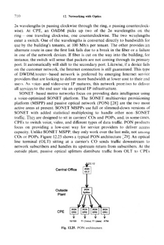
COs or POPs. Figure 12.25 shows a typical PON architecture [29]. An optical
line terminal (OLT) sitting at a carrier's CO sends traffic downstream to
network subscribers and handles its upstream return from subscribers. At the
outside plant, passive optical splitters distribute traffic from OLT to CPEs
Central Office
Outside
Plant
CPE
y v y
10/100 T1 (Voice) T1 (data) ATM
Fig. 12.25. PON architecture.