
Page 16 - Introduction to Marine Engineering
P. 16
4 Ships and machinery
Section looking to port Section looking forward
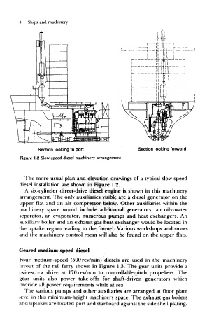
Figure 1.2 Slow-speed diesel machinery arrangement
The more usual plan and elevation drawings of a typical slow-speed
diesel installation are shown in Figure 1.2.
A six-cylinder direct-drive diesel engine is shown in this machinery
arrangement. The only auxiliaries visible are a diesel generator on the
upper flat and an air compressor, below. Other auxiliaries within the
machinery space would include additional generators, an oily-water
separator, an evaporator, numerous pumps and heat exchangers. An
auxiliary boiler and an exhaust gas heat exchanger would be located in
the uptake region leading to the funnel. Various workshops and stores
and the machinery control room will also be found on the upper flats.
Geared medium-speed diesel
Four medium-speed (500rev/min) diesels are used in the machinery
layout of the rail ferry shown in Figure 1.3. The gear units provide a
twin-screw drive at 170rev/min to controHable^pitch propellers. The
gear units also power take-offs for shaft-driven generators which
provide all power requirements while at sea.
The various pumps and other auxiliaries are arranged at floor plate
level in this minimum-height machinery space. The exhaust gas boilers
and uptakes are located port and starboard against the side shell plating.