
Page 22 - Introduction to Marine Engineering
P. 22
10 Diesel engines
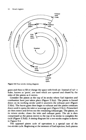
Figure 2.2 Four-stroke timing diagram
gases and then to fill or charge the space with fresh air. Instead of val*"js
holes, known as 'ports', are used which are opened and closed by the
sides of the piston as it moves.
Consider the piston at the top of its stroke where fuel injection and
combustion have just taken place (Figure 2.3(a)). The piston is forced
down on its working stroke until it uncovers the exhaust port (Figure
2.3(b)). The burnt gases then begin to exhaust and the piston continues
down until it opens the inlet or scavenge port (Figure 2.3(c)). Pressurised
air then enters and drives out the remaining exhaust gas. The piston, on
its return stroke, closes the inlet and exhaust ports. The air is then
compressed as the piston moves to the top of its stroke to complete the
cycle (Figure 2.3(d)). A timing diagram for a two-stroke engine is shown
in Figure 2.4.
The opposed piston cycle of operations is a special case of the
two-stroke cycle. Beginning at the moment of fuel injection, both pistons