
Page 253 - Introduction to Marine Engineering
P. 253
Steering gear 229
that circuit is isolated. The other system provides uninterrupted steering
and alarms are sounded and displayed.
Consider pump 1 in operation and pump 2 placed on automatic
reserve by the selector switch. If a leak develops in circuit 2 the float
chamber oil level will fall and proximity switch A on the monitor will be
activated to close the solenoid valve 2 which isolates circuit 2 and
bypasses the cylinders in that circuit. An alarm will also be given. If the
leak is in circuit 1 however, the float chamber oil level will fall further
until proximity switch B is activated. This will cut off the power supply to
motor 1 and solenoid valve 1 and connect the supply to motor 2 and
solenoid valve 2, thus isolating circuit 1. If pump 2 were running and
pump 1 in.reserve, a similar changeover would occur. While a two
cylinder system has been described this system will operate equally well
with four double acting cylinders.
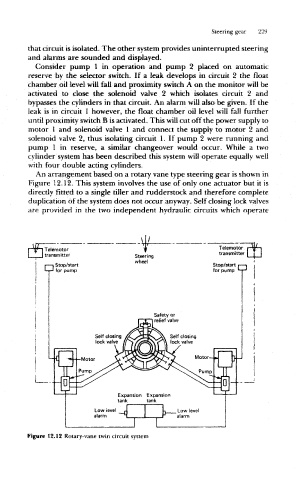
An arrangement based on a rotary vane type steering gear is shown in
Figure 12.12, This system involves the use of only one actuator but it is
directly fitted to a single tiller and rudderstock and therefore complete
duplication of the system does not occur anyway. Self closing lock valves
are provided in the two independent hydraulic circuits which operate
F W I Telemotor Telemotor r W i
L_ i transmitter Steering transmitter I I I
wheel
Stop/start Stop/start f—|
n for pump
Expansion Expansion
tank tank
Figure 12.12 Rotary-vane twin circuit system