
Page 28 - Introduction to Marine Engineering
P. 28
16 Diesel engines
Piston rod
Calibrated
spring
Drum
Linkage to
provide straight Piston
line movement
of stylus
Cylinder
Indicator
piston
Section showing
indicator piston
—I Coupling
*—' nut to
^vindicator fasten onto
cord indicator
cock
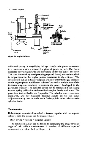
Figure 2.8 Engine indicator
calibrated spring. A magnifying linkage transfers the piston movement
to a drum on which is mounted a piece of paper or card. The drum
oscillates (moves backwards and forwards) under the pull of the cord.
The cord is moved by a reciprocating (up and down) mechanism which
is proportional to the engine piston movement in the cylinder. The
stylus draws out an indicator diagram which represents the gas pressure
on the engine piston at different points of the stroke, and the area of the
indicator diagram produced represents the power developed in the
particular cylinder. The cylinder power can be measured if the scaling
factors, spring calibration and some basic engine details are known. The
procedure is described in the Appendix. The cylinder power values are
compared, and for balanced loading should all be the same.
Adjustments may then be made to the fuel supply in order to balance the
cylinder loads.
Torsionmeter
If the torque transmitted by a shaft is known, together with the angular
velocity, then the power can be measured, i.e.
shaft power = torque x angular velocity
The torque on a shaft can be found by measuring the shear stress or
angle of twist with a torsionmeter. A number of different types of
torsionmeter are described in Chapter 15.