
Page 293 - Introduction to Marine Engineering
P. 293
Electrical equipment 267
Resistance
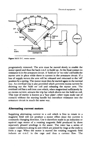
Figure 14.11 D.C. motor starter
progressively removed. The arm must be moved slowly to enable the
motor speed and thus the back e.m.f. to build up. At the final contact no
resistance is in the armature circuit. A 'hold on' or 'no volts' coil holds the
starter arm in place while there is current in the armature circuit. If a
loss of supply occurs the arm will be released and returned to the 'off
position by a spring. The motor must then be started again in the normal
way. An overload trip is also provided which prevents excess current by
shorting out the 'hold on* coil and releasing the starter arm. The
overload coil has a soft iron core which, when magnetised sufficiently by
an excess current, attracts the trip bar which shorts out the hold on coil.
This type of starter is known as a 'face plate'; other types make use of
contacts without the starting handle but introduce resistance into the
armature circuit in much the same way.
Alternating current motors
Supplying alternating current to a coil which is free to rotate in a
magnetic field will not produce a motor effect since the current is
constantly changing direction. Use is therefore made in an induction or
squirrel cage motor of a rotating magnetic field produced by three
separately phased windings in the stator. The rotor has a series of
copper conductors along its axis which are joined by rings at the ends to
form a cage. When the motor is started the rotating magnetic field
induces an e.m.f. in the cage and thus a current flow. The