
Page 302 - Introduction to Marine Engineering
P. 302
276 Electrical equipment
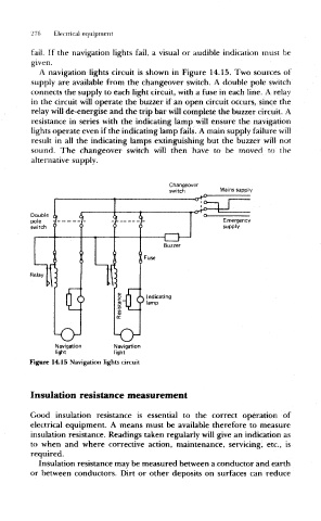
fail. If the navigation lights fail, a visual or audible indication must be
given.
A navigation lights circuit is shown in Figure 14.15. Two sources of
supply are available from the changeover switch. A double pole switch
connects the supply to each light circuit, with a fuse in each line, A relay
in the circuit will operate the buzzer if an open circuit occurs, since the
relay will de-energise and the trip bar will complete the buzzer circuit. A
resistance in series with the indicating lamp will ensure the navigation
lights operate even if the indicating lamp fails. A main supply failure will
result in all the indicating lamps extinguishing but the buzzer will not
sound. The changeover switch will then have to be moved to the
alternative supply.
Changeover
switch Mains supply
of?
Double
pole
switch
Relay
Kr
Navigation Navigation
light light
Figure 14.15 Navigation lights circuit
Insulation resistance measurement
Good insulation resistance is essential to the correct operation of
electrical equipment. A means must be available therefore to measure
insulation resistance. Readings taken regularly will give an indication as
to when and where corrective action, maintenance, servicing, etc., is
required.
Insulation resistance may be measured between a conductor and earth
or between conductors. Dirt or other deposits on surfaces can reduce