
Page 127 - Introduction to Microcontrollers Architecture, Programming, and Interfacing of The Motorola 68HC12
P. 127
104 Chapter 4 Assembly Language Programming
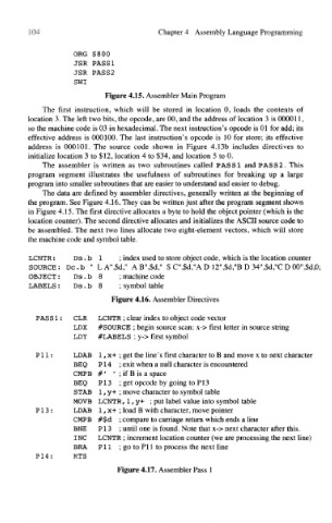
ORG $800
JSR PASSI
JSR PASS2
SWI
Figure 4.15. Assembler Main Program
The first instruction, which will be stored in location 0, loads the contents of
location 3. The left two bits, the opcode, are 00, and the address of location 3 is 000011,
so the machine code is 03 in hexadecimal. The next instruction's opcode is 01 for add; its
effective address is 000100. The last instruction's opcode is 10 for store; its effective
address is 000101. The source code shown in Figure 4.13b includes directives to
initialize location 3 to $12, location 4 to $34, and location 5 to 0.
The assembler is written as two subroutines called PAS SI and PASS 2. This
program segment illustrates the usefulness of subroutines for breaking up a large
program into smaller subroutines that are easier to understand and easier to debug.
The data are defined by assembler directives, generally written at the beginning of
the program. See Figure 4.16. They can be written just after the program segment shown
in Figure 4.15. The first directive allocates a byte to hold the object pointer (which is the
location counter). The second directive allocates and initializes the ASCII source code to
be assembled. The next two lines allocate two eight-element vectors, which will store
the machine code and symbol table.
LCNTR: Ds. b 1 ; index used to store object code, which is the location counter
SOURCE: Dc.b " LA",$d," AB",$d," S C",$d,"A D 12",$d,"B D 34",$d,"C D00",$d,0;
OBJECT: Ds.b 8 ; machine code
LABELS: Ds . b 8 ; symbol table
Figure 4.16. Assembler Directives
PASS 1: CLR LCNTR ; clear index to object code vector
LDX #SOURCE ; begin source scan: x-> first letter in source string
LDY #LABELS ; y-> first symbol
P11: LDAB 1, x+ ; get the line's first character to B and move x to next character
BEQ PI4 ; exit when a null character is encountered
CMPB #' ' ; if B is a space
BEQ PI3 ; get opcode by going to PI3
STAB 1, y+ ; move character to symbol table
MOVE LCNTR, 1,y+ ; put label value into symbol table
P13: LDAB 1, x+ ; load B with character, move pointer
CMPB #$d ; compare to carriage return which ends a line
BNE P13 ; until one is found. Note that x-> next character after this.
INC LCNTR ; increment location counter (we are processing the next line)
BRA PI 1 ; go to PI 1 to process the next line
P14: RTS
Figure 4.17. Assembler Pass 1