
Page 170 - Introduction to Microcontrollers Architecture, Programming, and Interfacing of The Motorola 68HC12
P. 170
6.1 Local Variables 147
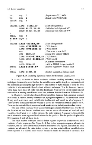
W: EQU 0 ; Input vector V(1),V(2)
WW: EQU 2 ; Input vector W(1),W(2)
SIZEA: EQU 4
*
STARTA: LEAS -SIZEA, SP ; Start of segment A
MOVW #$102,W,SP ; Initialize both bytes of VV
MOVW #$ 3 0 4, WW, SP ; Initialize both bytes of WW
*
TERM: EQU 0
SIZES: EQU 2
*
STARTS: LEAS -SIZEB, SP ; Start of segment B
LDAA VV-f SIZES, SP ; V(l) into A
LDAB WW+SIZEB,SP ;W(l)intoB
MUL ; First term is now in D
STD TERM, SP ; Store first term in TERM
LDAA VV+1+SIZEB,SP ; V(2) into A
LDAB WW+1+S1ZEB, SP ; W(2) into B
MUL ; Calculate second term
ADDD TERM,SP ; Add in TERM; dot product in D
ENDB: LE AS SIZ EB, S P ; End of segment B; balance stack
*
END A: LEAS SIZ EA, SP ; End of segment A; balance stack
Figure 6.13. Declaring Symbolic Names for Extended Local Access
It is easy to insert or delete variables without making mistakes, using this
technique, because the same line has the variable name and its length, as contrasted with
the last technique using the EQU directive. The number of bytes needed to store the local
variables is also automatically calculated with this technique. You do, however, have to
write three more lines of code with this technique. You have to invent some kind of
convention in naming variables to avoid this problem, but that is not too difficult to do.
In Chapter 3, we introduced nested local variables. Suppose that a program segment
B is nested in, that is, entirely contained in, a program segment A. An instruction inside
B may need to access a local variable that is allocated and bound for all of segment A.
There are two techniques that can be used to access the variable in B that is defined for A.
These are the extended local access and stack marker access techniques described below.
The idea of the extended local access technique assumes that there is a way to fix
the location of the desired variable over one or more allocations of stacked local
variables. See Figure 6.13. In this version, the outer segment A copies vectors into the
stack where the inner segment B calculates the dot product. The dot product is placed in
D by segment B and left there by A.
The stack marker technique uses an index register to provide a reference to local
variables of outer segments. See Figure 6.14. Just before a program segment allocates its
variables, the old value of the stack pointer is transferred to a register. Just after the local
variables are allocated, the value in this register is put into a stacked local variable for the
inner segment. It is called a stack marker because it marks the location of the stack that