
Page 26 - Introduction to Microcontrollers Architecture, Programming, and Interfacing of The Motorola 68HC12
P. 26
J.I Basic Computer Structure 3
microprocessor is called a microcomputer; and, if a complete computer is on a single
integrated circuit, that integrated circuit is called a single-chip microcontroller.
Some aspects of microcomputers apply to all computers. We will often discuss an
aspect of the computer and, of course, that aspect applies to microcontrollers, on which
we are concentrating. The microcomputer's, or microcontroller's, controller and data
operator is abbreviated MPU (microprocessor unit). The abbreviation CPU (central
processor unit) is often used to denote the controller and data operator, but that term leads
subtly to the idea that the CPU is central and most important; but this is misleading,
especially when a computer system has many MPUs, none of which is "central."
We now look more closely at the memory and the MPU. We can think of the
memory as a large number of cells, each able to store a 0 or a 1 —that is, a binary digit
or one bit of memory. The bits are grouped together in units called bytes, which consist
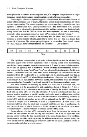
of 8 bits. Within a particular byte the bits are labeled b7,.. ., bO as shown.
Byte
The right-hand bits are called lower-order or least significant, and the left-hand bits
are called higher-order or most significant. There is nothing sacred about this labeling,
and, in fact, many computer manufacturers reverse it. A word in memory is the number
of bits that are typically read or written as a whole. In small microcomputers, a word is
one byte, so that the terms "word" and "byte" are often used interchangeably. In this text,
the 6812 can read an 8-bit or a 16-bit word, which is two bytes. In a 16-bit word, bits are
numbered from 15 (on the left) to 0 (on the right). In the memory, each byte has an
address between 0 and 2^ -1, where N is the total number of address bits. In the 6812, N
is essentially 16, so each address between 0 and 65,535 is described by its 16-bit binary
representation (see Appendix 1), although some 6812 versions can extend this range.
The MPU controls the memory by means of a clock and a read/write line, and
communicates to it by an address bus and a data bus, shown in Figure 1.1. A line or
wire carries one bit of information at each instance of time by the level of voltage on it.
Each line can carry a true (1) or a false (0) value. A bus is a collection of lines that can
move a word or an address in parallel, so that one bit of a word or address is on one line
of the bus. The data bus moves an 8-bit or 16-bit word to or from memory and from or
to the MPU, and the address bus moves a 16-bit address from the MPU to the memory.
A clock is a signal that is alternately a 0 and 1 (a square wave). A clock cycle is the
time interval from when the clock just becomes 0 until the next time it just becomes 0,
and the clock rate, or clock frequency, is the reciprocal of the clock cycle time.
Contemporary 6812 microcontrollers essentially use an 8 MHz clock.
In one clock cycle, the MPU can read a word from the memory by putting an
address on the address bus and making the read/write line 1 for the cycle and then
picking up the word on the data bus at the end of the cycle. It can also write a word into
the memory in one clock cycle by putting the address on the address bus and putting the
word on the data bus and making the read/write line 0 for the cycle. A read or a write to
memory is also called an access to memory.