
Page 33 - Introduction to Microcontrollers Architecture, Programming, and Interfacing of The Motorola 68HC12
P. 33
10 Chapter 1 Basic Computer Structure and the 68! 2
Figure 1.3 illustrates the implementation of the load and store instruction in a
simplified computer, which has two accumulators and four words of memory. The data
operator has accumulators A and B, and a memory has four words and a decoder. For the
instruction LDAA 2, which loads accumulator A with the contents of memory word 2,
the controller sends the address 2 on the address bus to the memory decoder; this decoder
enables word 2 to be read onto the data bus, and the controller asserts a control signal to
accumulator A to store the data on the data bus. The data in word 2 is not lost or
destroyed. For the instruction STAB 1, which stores accumulator B into the memory
word 1, the controller asserts a control signal to accumulator B to output its data on the
data bus, and the controller sends the address 1 on the address bus to the memory decoder;
this decoder enables word 1 to store the data on the data bus. The data in accumulator B is
not lost or destroyed.
The ADD instruction is used to add a number from memory to the number in an
accumulator, putting the result into the same accumulator. To add the contents of
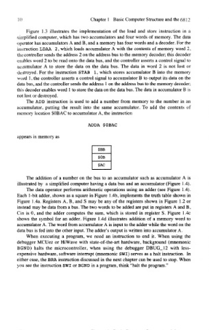
memory location $OB AC to accumulator A, the instruction
ADDA $OBAC
appears in memory as
The addition of a number on the bus to an accumulator such as accumulator A is
illustrated by a simplified computer having a data bus and an accumulator (Figure 1.4).
The data operator performs arithmetic operations using an adder (see Figure 1.4).
Each 1-bit adder, shown as a square in Figure 1.4b, implements the truth table shown in
Figure 1.4a. Registers A, B, and S may be any of the registers shown in Figure 1.2 or
instead may be data from a bus. The two words to be added are put in registers A and B,
Cin is 0, and the adder computes the sum, which is stored in register S. Figure 1.4c
shows the symbol for an adder. Figure 1.4d illustrates addition of a memory word to
accumulator A. The word from accumulator A is input to the adder while the word on the
data bus is fed into the other input. The adder's output is written into accumulator A.
When executing a program, we need an instruction to end it. When using the
debugger MCUez or HiWave with state-of-the-art hardware, background (mnemonic
BGND) halts the microcontroller, when using the debugger DBUG_12 with less-
expensive hardware, software interrupt (mnemonic SWI) serves as a halt instruction. In
either case, the BRA instruction discussed in the next chapter can be used to stop. When
you see the instruction SWI or BGND in a program, think "halt the program."