
Page 180 - Introduction to Naval Architecture
P. 180
166 STRENGTH
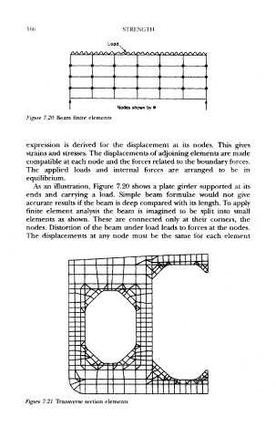
Figure 7.20 Beam finite elements
expression is derived for the displacement at its nodes. This gives
strains and stresses. The displacements of adjoining elements are made
compatible at each node and the forces related to the boundary forces.
The applied loads and internal forces are arranged to be in
equilibrium.
As an illustration, Figure 7.20 shows a plate girder supported at its
ends and carrying a load. Simple beam formulae would not give
accurate results if the beam is deep compared with its length. To apply
finite element analysis the beam is imagined to be split into small
elements as shown. These are connected only at their corners, the
nodes. Distortion of the beam under load leads to forces at the nodes.
The displacements at any node must be the same for each element
Figure 7.21 Transverse section elements