
Page 231 - Introduction to Naval Architecture
P. 231
216 PROPULSION
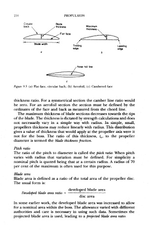
Figure 9.5 (a) Flat face, circular back; (b) Aerofoil; (c) Cambered face
thickness ratio. For a symmetrical section the camber line ratio would
be zero. For an aerofoil section the section must be defined by the
ordinates of the face and back as measured from the chord line.
The maximum thickness of blade sections decreases towards the tips
of the blade. The thickness is dictated by strength calculations and does
not necessarily vary in a simple way with radius. In simple, small,
propellers thickness may reduce linearly with radius. This distribution
gives a value of thickness that would apply at the propeller axis were it
not for the boss. The ratio of this thickness, t 0, to the propeller
diameter is termed the blade thickness fraction.
Pitch ratio
The ratio of the pitch to diameter is called the pitch ratio. When pitch
varies with radius that variation must be defined. For simplicity a
nominal pitch is quoted being that at a certain radius. A radius of 70
per cent of the maximum is often used for this purpose.
Blade area
Blade area is defined as a ratio of the total area of the propeller disc.
The usual form is:
developed blade area
Developed blade area ratio =
disc area
In some earlier work, the developed blade area was increased to allow
for a nominal area within the boss. The allowance varied with different
authorities and care is necessary in using such data. Sometimes the
projected blade area is used, leading to a projected blade area ratio.