
Page 45 - Introduction to Naval Architecture
P. 45
FLOTATION AND STABILITY 33
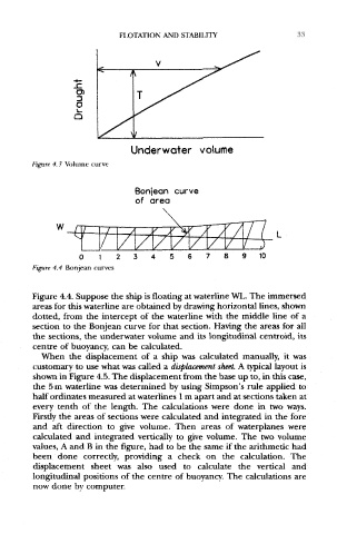
Figure 4,3 Volume curve
Figure 4.4 Bonjean curves
Figure 4.4. Suppose the ship is floating at waterline WL. The immersed
areas for this waterline are obtained by drawing horizontal lines, shown
dotted, from the intercept of the waterline with the middle line of a
section to the Bonjean curve for that section. Having the areas for all
the sections, the underwater volume and its longitudinal centroid, its
centre of buoyancy, can be calculated.
When the displacement of a ship was calculated manually, it was
customary to use what was called a displacement sheet. A typical layout is
shown in Figure 4.5. The displacement from the base up to, in this case,
the 5 m waterline was determined by using Simpson's rule applied to
half ordinates measured at waterlines 1 m apart and at sections taken at
every tenth of the length. The calculations were done in two ways.
Firstly the areas of sections were calculated and integrated in the fore
and aft direction to give volume. Then areas of waterplanes were
calculated and integrated vertically to give volume. The two volume
values, A and B in the figure, had to be the same if the arithmetic had
been done correctly, providing a check on the calculation. The
displacement sheet was also used to calculate the vertical and
longitudinal positions of the centre of buoyancy. The calculations are
now done by computer.