
Page 318 - Introduction to Petroleum Engineering
P. 318
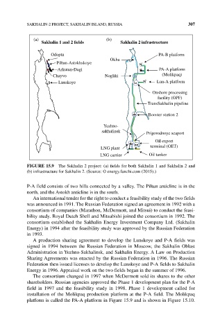
SAKHALIN‐2 PROJECT, SAKHALIN ISLAND, RUSSIA                     307

              (a)                           (b)
                  Sakhalin 1 and 2  elds         Sakhalin 2 infrastructure

                     Odoptu                                     PA-B platform
                                             Okha
                        Piltun-Astokhskoye
                        Arkutun-Dagi                             PA-A platform
                      Chayvo               Nogliki                (Molikpaq)
                        Lunskoye                                Lun-A platform
                                                              Onshore processing
                                                                facility (OPF)
                                                            TransSakhalin pipeline

                                                            Booster station 2

                                          Yuzhno-
                                          sakhalinsk        Prigorodnoye seaport

                                                               Oil export
                                         LNG plant           terminal (OET)
                                         LNG carrier         Oil tanker

            FIguRE 15.9  The Sakhalin 2 project: (a) fields for both Sakhalin 1 and Sakhalin 2 and
            (b) infrastructure for Sakhalin 2. (Source: © energy.fanchi.com (2015).)


            P‐A field consists of two hills connected by a valley. The Piltun anticline is in the
            north, and the Astokh anticline is in the south.
              An international tender for the right to conduct a feasibility study of the two fields
            was announced in 1991. The Russian Federation signed an agreement in 1992 with a
            consortium of companies (Marathon, McDermott, and Mitsui) to conduct the feasi-
            bility study. Royal Dutch Shell and Mitsubishi joined the consortium in 1992. The
            consortium established the Sakhalin Energy Investment Company Ltd. (Sakhalin
            Energy) in 1994 after the feasibility study was approved by the Russian Federation
            in 1993.
              A production sharing agreement to develop the Lunskoye and P‐A fields was
            signed in 1994 between the Russian Federation in Moscow, the Sakhalin Oblast
            Administration in Yuzhno‐Sakhalinsk, and Sakhalin Energy. A Law on Production
            Sharing Agreements was enacted by the Russian Federation in 1996. The Russian
            Federation then issued licenses to develop the Lunskoye and P‐A fields to Sakhalin
            Energy in 1996. Appraisal work on the two fields began in the summer of 1996.
              The consortium changed in 1997 when McDermott sold its shares to the other
            shareholders. Russian agencies approved the Phase 1 development plan for the P‐A
            field  in  1997  and  the  feasibility  study  in  1998.  Phase  1  development  called  for
            installation of the Molikpaq production platform at the P‐A field. The Molikpaq
            platform is called the PA‐A platform in Figure 15.9 and is shown in Figure 15.10.