
Page 290 - Machinery Component Maintenance
P. 290
272 Machinery Component Maintenance and Repair
Drive System Limitation
A given drive system has a certain rotor acceleration capability ex-
pressed in terms of the Wk2n2 value. This limiting value is generally part
of the machine specification describing the drive, since it depends pri-
marily on motor horsepower, motor type (squirrel-cage induction,
wound-rotor, DC), and drive line strength.
The specified Wk2n2 value may be used to determine the maximum
balancing speed (n) to which a rotor with a specific polar moment of iner-
tia (Wk2) can be accelerated; or conversely, to determine what maximum
Wk2 can be accelerated to a specified speed (n). (In each case the number
of runs per hour must stay within the maximum number of cycles
allowed .)
If a rotor is to be balanced which has a Wk2n2 value smaller than the
maximum specified for a given drive, the stated cycles per hour may gen-
erally be exceeded in an inverse ratio.
On occasion it may happen that a large diameter rotor, although still
within the weight capacity of the machine, cannot be accelerated to a
given balancing speed. This may be due to the fact that the rotor’s mass is
located at a large radius, thus creating a large polar moment of inertia.
As a result, a lower balancing speed may have to be selected.
A rotor’s polar moment of inertia (Wk2) is found by multiplying the
rotor weight (W) in pounds by the square of the radius-of-gyration (k) in
feet. The radius-of-gyration is the average of the radii from the shaft axis
of each infinitesimal part of the rotor. It may be approximated by multi-
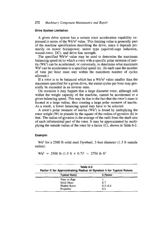
plying the outside radius of the rotor by a factor (C), shown in Table 6-2.
Example:
Wk2 for a 2500 lb solid steel flywheel, 3 foot diameter (1.5 ft outside
radius).
Wk2 = 2500 lb (1.5 ft X 0.7)2 = 2756 lb ft2
Table 6-2
Factor C for Approximating Radius of Gyration k for Typical Rotors
Typical Rotor C-Factor
’hbe or Pipe 1.
Solid Mass 0.7
Bladed Rotor 0.5-0.6
Propeller 0.4