
Page 38 - Make Your Own PCBs with EAGLE from Schematic Designs to Finished Boards
P. 38
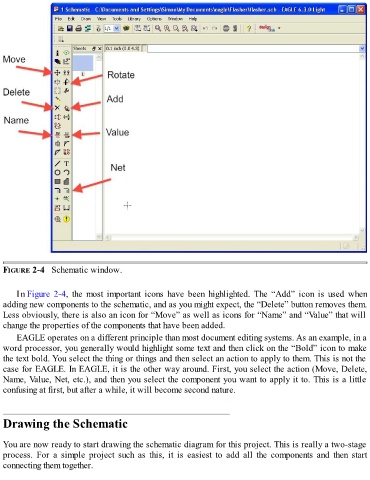
FIGURE 2-4   Schematic window.


      In Figure 2-4,  the  most  important  icons  have  been  highlighted.  The  “Add”  icon  is  used  when
  adding new components to the schematic, and as you might expect, the “Delete” button removes them.
  Less obviously, there is also an icon for “Move” as well as icons for “Name” and “Value” that will
  change the properties of the components that have been added.

      EAGLE operates on a different principle than most document editing systems. As an example, in a
  word processor, you generally would highlight some text and then click on the “Bold” icon to make
  the text bold. You select the thing or things and then select an action to apply to them. This is not the
  case for EAGLE. In EAGLE, it is the other way around. First, you select the action (Move, Delete,

  Name, Value, Net, etc.), and then you select the component you want to apply it to. This is a little
  confusing at first, but after a while, it will become second nature.


  Drawing the Schematic


  You are now ready to start drawing the schematic diagram for this project. This is really a two-stage
  process.  For  a  simple  project  such  as  this,  it  is  easiest  to  add  all  the  components  and  then  start
  connecting them together.