
Page 82 - Make Your Own PCBs with EAGLE from Schematic Designs to Finished Boards
P. 82
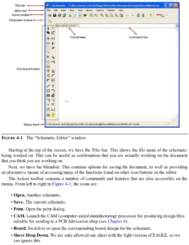
FIGURE 4-1   The “Schematic Editor” window.


      Starting at the top of the screen, we have the Title bar. This shows the file name of the schematic
  being worked on. This can be useful as confirmation that you are actually working on the document
  that you think you are working on.

      Next, we have the Menubar. This contains options for saving the document, as well as providing
  an alternative means of accessing many of the functions found on other icon buttons on the editor.

      The Action toolbar contains a number of commands and features that are also accessible on the
  menus. From left to right in Figure 4-1, the icons are


        • Open. Another schematic.

        • Save. The current schematic.

        • Print. Open the print dialog.
        • CAM. Launch the CAM (computer-aided manufacturing) processor for producing design files

          suitable for sending to a PCB fabrication shop (see Chapter 6).

        • Board. Switch to or open the corresponding board design for the schematic.
        • Sheet Drop Down. We are only allowed one sheet with the light version of EAGLE, so we
          can ignore this.