
Page 332 - Making things move_ DIY mechanisms for inventors, hobbyists, and artists
P. 332
Chapter 10 Projects 309
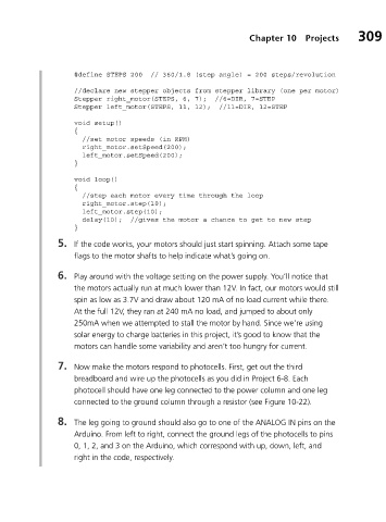
#define STEPS 200 // 360/1.8 (step angle) = 200 steps/revolution
//declare new stepper objects from stepper library (one per motor)
Stepper right_motor(STEPS, 6, 7); //6=DIR, 7=STEP
Stepper left_motor(STEPS, 11, 12); //11=DIR, 12=STEP
void setup()
{
//set motor speeds (in RPM)
right_motor.setSpeed(200);
left_motor.setSpeed(200);
}
void loop()
{
//step each motor every time through the loop
right_motor.step(10);
left_motor.step(10);
delay(10); //gives the motor a chance to get to new step
}
5. If the code works, your motors should just start spinning. Attach some tape
flags to the motor shafts to help indicate what’s going on.
6. Play around with the voltage setting on the power supply. You’ll notice that
the motors actually run at much lower than 12V. In fact, our motors would still
spin as low as 3.7V and draw about 120 mA of no load current while there.
At the full 12V, they ran at 240 mA no load, and jumped to about only
250mA when we attempted to stall the motor by hand. Since we’re using
solar energy to charge batteries in this project, it’s good to know that the
motors can handle some variability and aren’t too hungry for current.
7. Now make the motors respond to photocells. First, get out the third
breadboard and wire up the photocells as you did in Project 6-8. Each
photocell should have one leg connected to the power column and one leg
connected to the ground column through a resistor (see Figure 10-22).
8. The leg going to ground should also go to one of the ANALOG IN pins on the
Arduino. From left to right, connect the ground legs of the photocells to pins
0, 1, 2, and 3 on the Arduino, which correspond with up, down, left, and
right in the code, respectively.