
Page 534 -
P. 534
Chapter 13 Building Information Systems 533
from processes. A separate programming procedure must be written every time
someone wants to take an action on a particular piece of data. The procedures
act on data that the program passes to them.
The primary tool for representing a system’s component processes and the
flow of data between them is the data flow diagram (DFD). The data flow dia-
gram offers a logical graphic model of information flow, partitioning a system
into modules that show manageable levels of detail. It rigorously specifies the
processes or transformations that occur within each module and the interfaces
that exist between them.
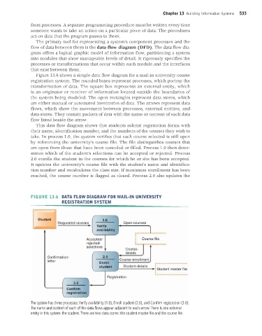
Figure 13.6 shows a simple data flow diagram for a mail-in university course
registration system. The rounded boxes represent processes, which portray the
transformation of data. The square box represents an external entity, which
is an originator or receiver of information located outside the boundaries of
the system being modeled. The open rectangles represent data stores, which
are either manual or automated inventories of data. The arrows represent data
flows, which show the movement between processes, external entities, and
data stores. They contain packets of data with the name or content of each data
flow listed beside the arrow.
This data flow diagram shows that students submit registration forms with
their name, identification number, and the numbers of the courses they wish to
take. In process 1.0, the system verifies that each course selected is still open
by referencing the university’s course file. The file distinguishes courses that
are open from those that have been canceled or filled. Process 1.0 then deter-
mines which of the student’s selections can be accepted or rejected. Process
2.0 enrolls the student in the courses for which he or she has been accepted.
It updates the university’s course file with the student’s name and identifica-
tion number and recalculates the class size. If maximum enrollment has been
reached, the course number is flagged as closed. Process 2.0 also updates the
FIGURE 13.6 DATA FLOW DIAGRAM FOR MAIL-IN UNIVERSITY
REGISTRATION SYSTEM
The system has three processes: Verify availability (1.0), Enroll student (2.0), and Confirm registration (3.0).
The name and content of each of the data flows appear adjacent to each arrow. There is one external
entity in this system: the student. There are two data stores: the student master file and the course file.
MIS_13_Ch_13 global.indd 533 1/17/2013 2:31:23 PM