
Page 158 - Managing Global Warming
P. 158
Separator - superheater
P = 5.88 MPa P = 1.15 MPa 9
T = 274°C 0 IPT 8 T = 250°C LPT
Steam generator 1 2 3 Deaerator 4 5 6 7 Condenser
P c = 3.9 kPa
Pump
T fw = 223°C x 1 x 2 x 3
x 4 x 5 x 6
Feed x 7
pump
HPH 3 HPH 2 HPH 1 LPH 4 LPH 3 LPH 2 LPH 1
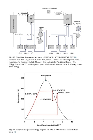
Fig. 4.3 Simplified thermodynamic layout of 1000-MW el VVER-1000 PWR NPP [1].
Based on data from Grigor’ev VA, Zorin VM, editors. Thermal and nuclear power plants.
Handbook, (in Russian). 2nd ed. Moscow: Energoatomizdat Publishing House; 1988.
625 pp; Margulova TC. Nuclear power plants, (in Russian). Moscow: Izdat Publishing House;
1955. 289 pp.
Fig. 4.4 Temperature-specific entropy diagram for VVER-1000 Rankine steam-turbine
cycle [1].