
Page 565 - 04. Subyek Engineering Materials - Manufacturing, Engineering and Technology SI 6th Edition - Serope Kalpakjian, Stephen Schmid (2009)
P. 565
Section 20.5 Direct Manufacturing and Rapid Tooling
6. Shrinkage due to solidification or thermal contraction can be compensated for
automatically through software to produce tooling of the proper size and, in
turn, to produce the desired parts.
The main shortcoming of rapid tooling is the potentially reduced tool or pattern life
(compared to those obtained from machined tool and die materials, such as tool
steels or tungsten carbides).
The simplest method of applying rapid-prototyping operations to other manu-
facturing processes is in the direct production of patterns or molds. As an example,
O
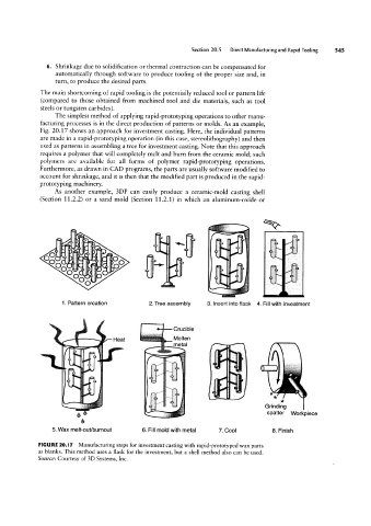
Fig. 20.17 shows an approach for investment casting. Here, the individual patterns
are made in a rapid-prototyping operation (in this case, stereolithography) and then
used as patterns in assembling a tree for investment casting. Note that this approach
requires a polymer that will completely melt and burn from the ceramic mold; such
polymers are available for all forms of polymer rapid-prototyping operations.
*P
Furthermore, as drawn in CAD programs, the parts are usually software modified to
account for shrinkage, and it is then that the modified part is produced in the rapid-
prototyping machinery.
As another example, 3DP can easily produce a ceramic-mold casting shell
(Section 11.2.2) or a sand mold (Section 11.2.1) in which an aluminum-oxide or
,,..
_“1¢J-;|fQ, -6 ‘ 'fi -.
-§|_»=#1_1-__» 3` ;,= it -T. sl
l =
si* ir ici' -a' T40 » f f
i
_ bl 'eg
A
o O v 1 -» .P _i 0 ,I » O ._ " -> - r i I l
_
G
i
O
2. Tree assembly
1. Pattern creation Heat Crucible 3. Insert into flask 4. Fill with investment
, !
Molten
metal
-
” -
6 Grinding Workpiece
spatter
6
5. Wax melt-ouifburnout 6. Fill mold with metal 7. Cool 8. Finish
FIGURE 20.I 7 Manufacturing steps for investment casting with rapid-prototyped wax parts
as blanks. This method uses a flask for the investment, but a shell method also can be used.
Source: Courtesy of 3D Systems, Inc.