
Page 321 - Marine Structural Design
P. 321
Chapter I4 qffshore Structures Under Impact Loads 297
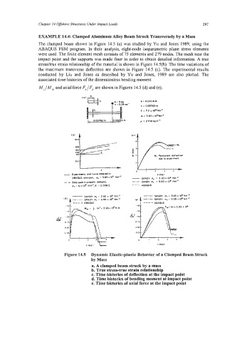
EXAMPLE 14.4: Clamped Aluminum Alloy Beam Struck Transversely by a Mass
The clamped beam shown in Figure 14.5 (a) was studied by Yu and Jones 1989, using the
ABAQUS FEM program. In their analysis, eight-node isoparametric plane stress elements
were used. The finite element mesh consists of 75 elements and 279 nodes. The mesh near the
impact point and the supports was made finer in order to obtain detailed information. A true
stresshe strain relationship of the material is shown in Figure 14.5(b). The time variations of
the maximum transverse deflection are shown in Figure 14.5 (c). The experimental results
conducted by Liu and Jones as described by Yu and Jones, 1989 are also plotted. The
associated time histories of the dimensionless bending moment
Mz/M, and axial force F,/F, are shown in Figures 14.5 (d) and (e).
(0) b A
Ufh .m:5k0 b i 0.01016 m
Y i 5.34 mi' h i 0.00752 m
E i 7.2 I 10"Nm-2
u.:3.93x10*Hn'*
c 0.00762m 0002$4m p : 2700I~am'~
200 y , / w, Permonmt ddlrIion
due IO aIFulment
Figure 14.5 Dynamic Elastic-plastic Behavior of a Clamped Beam Struck
by Mass
a. A clamped beam struck by a mass
b. True stress-true strain relationship
c. Time histories of deflection at the impact point
d. Time histories of bending moment at impact point
e. Time histories of axial force at the impact point