
Page 157 - Master Handbook of Acoustics
P. 157
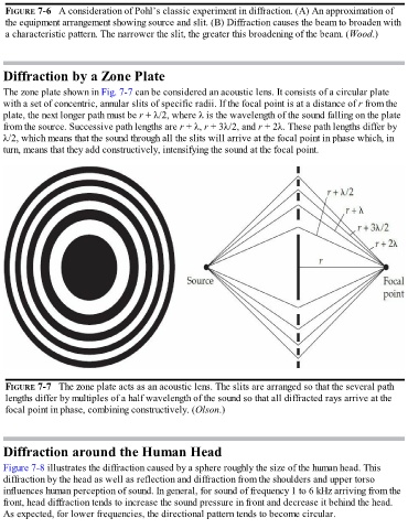
FIGURE 7-6   A consideration of Pohl’s classic experiment in diffraction. (A) An approximation of

   the equipment arrangement showing source and slit. (B) Diffraction causes the beam to broaden with
   a characteristic pattern. The narrower the slit, the greater this broadening of the beam. (Wood.)


  Diffraction by a Zone Plate

  The zone plate shown in Fig. 7-7 can be considered an acoustic lens. It consists of a circular plate

  with a set of concentric, annular slits of specific radii. If the focal point is at a distance of r from the
  plate, the next longer path must be r + λ/2, where λ is the wavelength of the sound falling on the plate
  from the source. Successive path lengths are r + λ, r + 3λ/2, and r + 2λ. These path lengths differ by
  λ/2, which means that the sound through all the slits will arrive at the focal point in phase which, in
  turn, means that they add constructively, intensifying the sound at the focal point.


   FIGURE 7-7   The zone plate acts as an acoustic lens. The slits are arranged so that the several path
   lengths differ by multiples of a half wavelength of the sound so that all diffracted rays arrive at the
   focal point in phase, combining constructively. (Olson.)


  Diffraction around the Human Head

  Figure 7-8 illustrates the diffraction caused by a sphere roughly the size of the human head. This
  diffraction by the head as well as reflection and diffraction from the shoulders and upper torso
  influences human perception of sound. In general, for sound of frequency 1 to 6 kHz arriving from the
  front, head diffraction tends to increase the sound pressure in front and decrease it behind the head.

  As expected, for lower frequencies, the directional pattern tends to become circular.