
Page 51 - Mechanical Engineers' Handbook (Volume 2)
P. 51
40 Input and Output Characteristics
k total k k 2
1
s s
3.4 Computing Impedance or Admittance at an Input or Output
There are basically two ways in which an input or output admittance can be computed. The
first, and most direct, is to compute the transfer function between the effort and the flow at
the driving point and take the derivative with respect to the flow. For a mechanical rotational
system, for example, torque as a function of angular velocity is expressed and differentiated
with respect to angular velocity. This method must be used if the system being considered
is nonlinear because the derivative must be taken at an operating point. If the system is
linear, then the ratio of flow or effort will suffice; in the rotational system, the impedance is
simply the ratio / (torque/speed).
The second method takes the impedances of the elements one at a time and combines
them. This approach is particularly useful for linear (or linearized) systems. The question
then arises of determining the impedance of any sources in the subsystem being considered.
Flow sources, such as current sources, velocity sources, angular velocity sources, and fluid
flow sources, all have the relationship flow constant. Their impedance is therefore infinite
(Z flow source ) because any change in effort results in zero change in flow. Effort sources,
such as voltage sources, force sources, torque sources, and pressure sources, will provide
any flow to maintain the effort required; the change in effort for a change in flow remains
zero, so their impedance is Z effort source 0. An effort source therefore represents a short
circuit from an impedance point of view; it connects together two nodes that were separate.
A flow source represents a null element; since its impedance is infinite, it represents an open
circuit. Flow sources are simply removed in impedance calculations.
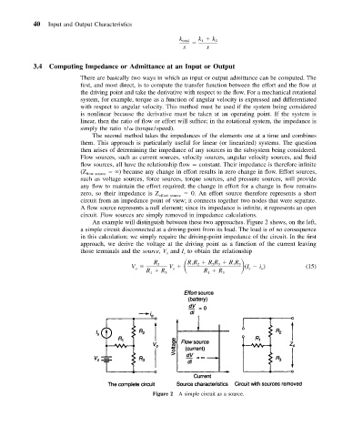
An example will distinguish between these two approaches. Figure 2 shows, on the left,
a simple circuit disconnected at a driving point from its load. The load is of no consequence
in this calculation; we simply require the driving-point impedance of the circuit. In the first
approach, we derive the voltage at the driving point as a function of the current leaving
those terminals and the source, V and I to obtain the relationship
s
s
R V R R RR RR
V 3 s 1 2 2 3 1 3 (I i ) (15)
s
o
o
R R 3 R R 3
1
1
Figure 2 A simple circuit as a source.