
Page 134 - Mechanical Engineers' Handbook (Volume 4)
P. 134
2 Exergy Analysis 123
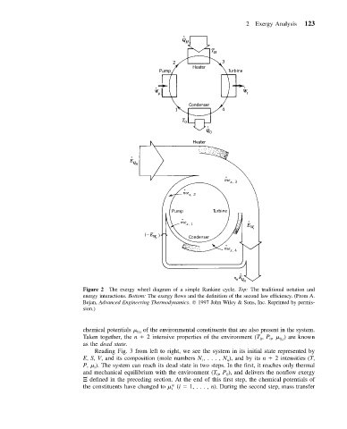
Figure 2 The exergy wheel diagram of a simple Rankine cycle. Top: The traditional notation and
energy interactions. Bottom: The exergy flows and the definition of the second law efficiency. (From A.
Bejan, Advanced Engineering Thermodynamics. 1997 John Wiley & Sons, Inc. Reprinted by permis-
sion.)
chemical potentials of the environmental constituents that are also present in the system.
0,i
Taken together, the n 2 intensive properties of the environment (T , P , ) are known
0,i
0
0
as the dead state.
Reading Fig. 3 from left to right, we see the system in its initial state represented by
E, S, V, and its composition (mole numbers N ,..., N ), and by its n 2 intensities (T,
1
n
P, ). The system can reach its dead state in two steps. In the first, it reaches only thermal
i
and mechanical equilibrium with the environment (T , P ), and delivers the nonflow exergy
0
0
defined in the preceding section. At the end of this first step, the chemical potentials of
the constituents have changed to * (i 1, . .., n). During the second step, mass transfer
i