
Page 244 - Mechanical Engineers' Handbook (Volume 4)
P. 244
8 Heat Transfer 233
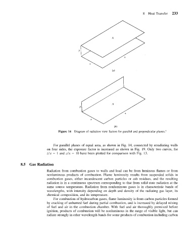
Figure 14 Diagram of radiation view factors for parallel and perpendicular planes. 1
For parallel planes of equal area, as shown in Fig. 14, connected by reradiating walls
on four sides, the exposure factor is increased as shown in Fig. 19. Only two curves, for
z/x 1 and z/x 10 have been plotted for comparison with Fig. 13.
8.5 Gas Radiation
Radiation from combustion gases to walls and load can be from luminous flames or from
nonluminous products of combustion. Flame luminosity results from suspended solids in
combustion gases, either incandescent carbon particles or ash residues, and the resulting
radiation is in a continuous spectrum corresponding to that from solid-state radiation at the
same source temperature. Radiation from nonluminous gases is in characteristic bands of
wavelengths, with intensity depending on depth and density of the radiating gas layer, its
chemical composition, and its temperature.
For combustion of hydrocarbon gases, flame luminosity is from carbon particles formed
by cracking of unburned fuel during partial combustion, and is increased by delayed mixing
of fuel and air in the combustion chamber. With fuel and air thoroughly premixed before
ignition, products of combustion will be nonluminous in the range of visible light, but can
radiate strongly in other wavelength bands for some products of combustion including carbon