
Page 530 - Mechanical Engineers' Handbook (Volume 4)
P. 530
7 Examples of Cryogenic Processing 519
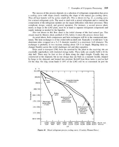
The success of this process depends on a selection of refrigerant composition that gives
a cooling curve with shape closely matching the shape of the natural gas cooling curve.
Thus all heat transfer will be across small Ts. This is shown in Fig. 41, a cooling curve
for a mixed refrigerant cycle. The need to deal with a mixed refrigerant and to control the
composition of the refrigerant mixture are the major difficulties with these processes. They
complicate design, control, and general operation. For instance, a second process plant,
nearly as large as the LNG plant, must be at hand to separate refrigerant components and
supply makeup as needed by the liquefier.
Also not shown in this flow sheet is the initial cleanup of the feed natural gas. This
stream must be filtered, dried, purified of CO before it enters the process shown here.
2
As noted above, both compressors and heat exchangers will be at the commercial max-
imum. The heat exchanger is of the coiled-tube-in-shell sort. Typically it would have ⁄4-in.
3
aluminum tubes wrapped on a 2–3 ft diameter mandrel to a maximum 14-ft diameter. The
exchanger is probably in two sections totaling about 120 ft in length. Shipping these ex-
changer bundles across the world challenges rail and ship capacities.
Ships used to transport LNG from the terminal by the plant to the receiving site are
essentially supertankers with insulated storage tanks. These tanks are usually built to fit the
ship hull. There may be four or five of them along the ship’s length. Usually they are
constructed at the shipyard, but in one design they are built in a separate facility, shipped
by barge to the shipyard, and hoisted into position. Boiloff from these tanks is used as fuel
for the ship. On long ocean hauls 6–10% of the LNG will be so consumed. In port the
Figure 41 Mixed refrigerant process cooling curve. (Courtesy Plenum Press.)