
Page 547 - Mechanical Engineers' Handbook (Volume 4)
P. 547
536 Indoor Environmental Control
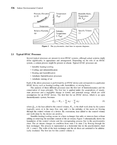
Pressure, Elevation Temperature Humidity Ratio,
(p, H) Ratio (T ) Temperature
DB
(W, T )
Humidity dp
Temperature
Relative Humidity Enthalpy, Specific Volume
(φ) Temperature (v)
(i ,T WB )
Figure 2 The psychrometric chart lines in separate diagrams.
2.1 Typical HVAC Processes
Several typical processes are present in most HVAC systems, although actual systems might
differ significantly in appearance and arrangement. Depending on the role of an HVAC
system, a certain process might be present or absent. Typical HVAC processes are
• Sensible heating/cooling
• Cooling and dehumidification
• Heating and humidification
• Adiabatic humidification processes
• Adiabatic mixing of air
Each of the above processes is performed by an HVAC device and corresponds to a particular
HVAC device such as heating/cooling coils, humidifiers, or mixing boxes.
The analysis of these different processes uses the first law of thermodynamics and the
conservation of mass principle. The first law is applied under the assumptions of steady-
state processes and a negligible change in kinetic and potential energy, which are valid
assumptions for an HVAC device. The first law for an HVAC device, which is an open
thermodynamic system, becomes
˙
Q ˙ CV W CV ˙ mi ˙ mi (9)
a
a
out in
˙
˙
where Q CV is the heat added to the control volume, W CV is the shaft work done by the system
(typically zero), ˙m is the mass flow rate, and i is the enthalpy of the moist air flowing
through the control volume of a device. By convention, heat added to the control volume
and work done by the device are positive.
Sensible heating/cooling occurs in a heat exchanger that adds or removes heat without
adding or removing the moisture content of the air stream. Figure 3 schematically shows the
boundaries of the control volume and the corresponding process line in the psychrometric
chart. The air stream changes its condition from state 1 to state 2 by flowing through the
heat exchanger. The process is represented as a horizontal line in the psychrometric chart
(W const.). The walls of the heat exchanger and the air ducts are assumed to be adiabat-
ically insulated. The first law for this control volume is