
Page 105 - Mechanics Analysis Composite Materials
P. 105
90 Mechanics and analysis of composite materials
Similar derivation for an in-plane shear yields
(3.90)
Dependencies of E2 and G12 on the fiber volume fraction corresponding to
Eqs. (3.89) and (3.90) are shown in Figs. 3.36 and 3.37 (dotted lines). As can be
seen, the second-order model of a ply provides better agreement with experimental
results than the first-order model. This agreement can be further improved if
we take a more realistic microstructure of the material. Consider the actual
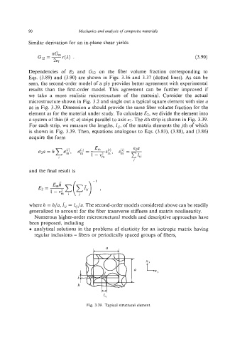
microstructure shown in Fig. 3.2 and single out a typical square element with size a
as in Fig. 3.39. Dimension a should provide the same fiber volume fraction for the
element as for the material under study. To calculate E2, we divide the element into
a system of thin (h << a) strips parallel to axis x2. The ith strip is shown in Fig. 3.39.
For each strip, we measure the lengths, lo, of the matrix elements the jth of which
is shown in Fig. 3.39. Then, equations analogous to Eqs. (3.83), (3.88), and (3.86)
acquire the form
and the final result is
where h = h/a, Gj = Io/a. The second-order models considered above can be readily
generalized to account for the fiber transverse stiffness and matrix nonlinearity.
Numerous higher-order microstructural models and descriptive approaches have
been proposed, including
0 analytical solutions in the problems of elasticity for an isotropic matrix having
regular inclusions - fibers or periodically spaced groups of fibers,
Fig. 3.39. Typical structural element.