
Page 62 - Mechanics of Microelectromechanical Systems
P. 62
1. Stiffness basics 49
It is clear that the thicknesses produced by Eqs. (1.190) and (1.192) are equal
only for one relationship between the two factors, and Expressing one
of the factors in terms of the other implies solving a third degree equation
(resulting from equating the right hand sides of Eqs. (1.190)) and (1.192)),
which will have one real solution. Figure 1.26 is the plot of the thickness
ratio:
and it can be seen that this ratio spans the (0.8 1.2) range. It can also be
seen that due to its monotonic variation, the ratio can only be equal to 1 for
one pair, and the two thicknesses are identical solely for that unique
combination.
6.2 Serially-Connected Members
A problem directly resulting from the previous one addresses the case
where two or more different structural members are connected serially, as
depicted in the structure sketched in Fig. 1.27. The case studied in the
previous subsection 6.1 offers the explanation with respect to the necessity of
approaching the topic of serially-connected components. When the two
different components that are sandwiched together do not have identical
lengths, the equivalent rigidities can be calculated as shown in paragraph 6.1
for the overlapping length. This equivalent member will behave as a new
portion that is serially connected to the remaining segments that are
homogeneous.
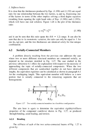
Figure 1.27 Two serially-connected members in a fixed-free configuration
The aim here is again to determine the equivalent rigidity/stiffness
properties of the compound cantilever shown in Fig. 1.27, as produced
through bending, axial loading, and torsion.
6.2.1 Bending
The stiffness of each of the two series-connected beams of Fig. 1.27 is
given by: