
Page 45 - Mechatronic Systems Modelling and Simulation with HDLs
P. 45
34 2 PRINCIPLES OF MODELLING AND SIMULATION
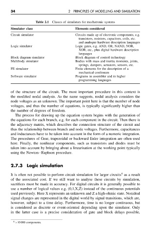
Table 2.1 Classes of simulators for mechatronic systems
Simulator class Elements considered
Circuit simulator Circuits made up of electronic components, e.g.
transistors, resistors, capacitors, coils, etc.
and analogue hardware description languages
Logic simulator Logic gates, e.g. AND, OR, NAND, NOR,
XOR, etc., plus digital hardware description
languages
Block diagram simulator Block diagram of control technology
Multibody simulator Bodies with mass and inertia moments, joints,
springs, dampers, actuators, sensors, etc.
FE simulator Finite elements for the description of a
mechanical continuum
Software simulator Programs in assembler and in higher
programming languages
of the structure of the circuit. The most important procedure in this context is
the modified nodal analysis. As the name suggests, nodal analysis considers the
node voltages as an unknown. The important point here is that the number of node
voltages, and thus the number of equations, is typically significantly higher than
the number of degrees of freedom.
The process for drawing up the equation system begins with the generation of
the equations for each branch, e.g. for each component in the circuit. Then there is
the adjacency matrix, which describes the connection structure of the circuit and
thus the relationship between branch and node voltages. Furthermore, capacitances
and inductances have to be taken into account in the form of a numeric integration.
The procedures of Gear, trapezoidal or backward Euler integration are often used
here. Finally, the nonlinear components, such as transistors and diodes must be
taken into account by bringing about a linearisation at the working point typically
using the Newton–Raphson procedure.
2.7.3 Logic simulation
4
It is often not possible to perform circuit simulation for larger circuits as a result
of the associated cost. If we still want to analyse these circuits by simulation,
sacrifices must be made in accuracy. For digital circuits it is generally possible to
use a number of logical values e.g. (0,1,X,Z) instead of the continuous potentials
used previously. Here X represents an unknown and Z a high-ohmic state. Nonideal
signal changes are represented in the digital world by signal transitions, which are,
however, subject to a time delay. Furthermore, time is no longer continuous, but
is considered as discrete or event-oriented depending upon the simulator. Only
in the latter case is a precise consideration of gate and block delays possible,
4 >10 000 components.