
Page 27 - Mechatronics for Safety Security and Dependability in a New Era
P. 27
Ch03-I044963.fm Page 10 Tuesday, August 1, 2006 12:24 PM
Ch03-I044963.fm
10 10 Page 10 Tuesday, August 1,2006 12:24 PM
disturbed a position of subject's hand from an equilibrium position to the other, and measured the
restoring force after new equilibrium had been reached. They gave us the conclusion that the
appeared force field was almost equivalent to it of spring. The hand stiffness could be represented
graphically by an ellipse shape. The major axis of ellipse was typically oriented in the direction of a
straight line that connects the shoulder and middle point of the upper arm. While the stiffness
specifies the exerted force due to a position deviation in static equilibrium, the dynamic relation
between small force and position variations is explained by the impedance. Some useful results on
the impedance of hand have been reported by Dolan (1993) and Tsuji (1995). Both teams used a
robot to exert small varying forces on the hand and assumed a second-order mass viscosity stiffness
model to fit the force and position data. Flash and Mussa-lvaldi (1990) showed that the shoulder
stiffness varied with the stiffness provided by the biarticular muscles that was used to obtain a polar
direction of the stiffness ellipse (towards the shoulder). They were approximately found in their
measurements. In general, arm impedance is the resultant of passive dynamics of the arm, intrinsic
impedance of activated muscles and reflexive contributions. However, the characteristic of a wrist
has not been made clear.
hi this report, we described the verification results of operational performance and synthetic view on
new type of handle, which was efficient to keep operator's posture stable with simple operation as the
forward and backward motion of operator's arm.
STRUCTUR E O F LIN K TYP E HANDL E
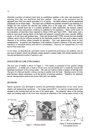
The new type of handle is shown in Figure 1. This handle is composed of four parallel linkage
mechanisms. A handle axis is fixed to driven joint, and the handle axis is rotated by forward and
backward movement of two riving joints. The rods are used to restrict a motion of driving joint.
The grip of a link type handle is always moving in parallel with the body. Bending motion of wrist
joint becomes almost unnecessary in all the process of steering operation. Therefore, the stabilized
natural seating position posture can always held, and it can operate.
METHODS
Special equipment was developed to examine the performance characteristics of our newly device
electric cart maneuvering mechanism. Two torque sensors[20 N • m] and two potentiometers were
attached to the steering shaft and one side of the handle grips. The measured values of the steering
angle and bending angle of the wrist were analyzed as a function of the turning torque forced to the
R
Driving joint
Driving joint
Y
T S
S
T
R
Rod w
Driven joint
w
Steering shaft X
Steering shaft
W W
Fixation
shaft
Fixation shaft
Figure 2: Subject position on
Figure 1: Link type handle
measurement device