
Page 180 - Methods For Monitoring And Diagnosing The Efficiency Of Catalytic Converters A Patent - oriented Survey
P. 180
I62 Methods for Monitoring and Diagnosing the Efficiency of Catalytic Converters
I CPU
temp.
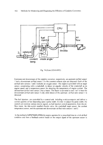
Fig. 74 (from US5414995)
Upstream and downstream of the catalytic converter, respectively, an upstream air/fbel sensor
1 and a downstream air/fuel sensor 2 in the common exhaust pipe are disposed. Each of the
air/fuel ratio sensors 1 and 2 includes an oxygen sensor. The engine is provided with an angle
sensor, cooperating with a crankshaft, to detect an angular velocity of the crankshaft as an
engine speed, and a temperature sensor for detecting the temperature of engine coolant. The
downstream air/fbel ratio sensor 2 has a heater. The heater is activated to turn "on" to heat the
downstream air/fbel ratio sensor 2 only while failure of the upstream aidfuel ratio sensor 1 is
detected.
The fuel injectors are controlled by a control unit including a microcomputer and deliver a
correct quantity of fuel depending upon a pulse width. In order to adjust the pulse width, the
control unit receives various electric signals, as &el injection control parameters, fiom the air-
flow meter, the idle-switch installed throttle valve, the crankshaft angle sensor, the coolant
temperature sensor, and the upstream and downstream aidfuel ratio sensors 1 and 2.
In the method of JPS272329 (1993) the engine operates for a prescribed time in a rich aidfie1
condition and then a feedback-control based on the output signal of the upstream sensor is