
Page 188 - Methods For Monitoring And Diagnosing The Efficiency Of Catalytic Converters A Patent - oriented Survey
P. 188
170 Methods for Monitoring and Diagnosing the Eficiency of Catalytic Converters
2
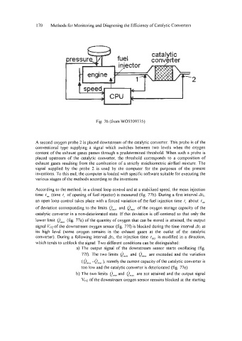
Fig. 76 (from W09309335)
A second oxygen probe 2 is placed downstream of the catalytic converter. This probe is of the
conventional type supplying a signal which switches between two levels when the oxygen
content of the exhaust gases passes through a predetermined threshold. When such a probe is
placed upstream of the catalytic converter, the threshold corresponds to a composition of
exhaust gases resulting from the combustion of a strictly stoichiometric aidfuel mixture. The
signal supplied by the probe 2 is used by the computer for the purposes of the present
inventions. To this end, the computer is loaded with specific software suitable for executing the
various stages of the methods according to the inventions.
According to the method, in a closed loop control and at a stabilized speed, the mean injection
time I,, (time I, of opening of fuel injector) is measured (fig. 77b). During a first interval At!,
an open loop control takes place with a forced variation of the fie1 injection time t, about I,,
of deviation corresponding to the limits e,,, and om, of the oxygen storage capacity of the
catalytic converter in a non-deteriorated state. If this deviation is off-centered so that only the
lower limit Qm," (fig. 77e) of the quantity of oxygen that can be stored is attained, the output
signal Voz of the downstream oxygen sensor (fig. 77f) is blocked during the time interval Atr at
its high level (some oxygen remains in the exhaust gases at the outlet of the catalytic
converter). During a following interval At2, the injection time fdZ is modified in a direction,
which tends to unblock the signal. Two different conditions can be distinguished:
a) The output signal of the downstream sensor starts oscillating (fig.
770. The two limits om,, and om% are exceeded and the variation
(om,, -om," namely the current capacity of the catalytic converter is
),
too low and the catalytic converter is deteriorated (fig 77e)
b) The two limits em," and om, are not attained and the output signal
VOZ of the downstream oxygen sensor remains blocked at the starting