
Page 115 - Modelling in Transport Phenomena A Conceptual Approach
P. 115
4.5. FLOW IN CIRCULAR PIPES 95
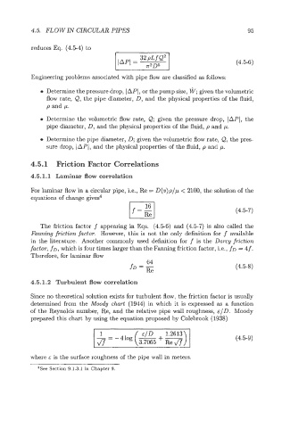
reduces Eq. (4.54) to
(4.56)
Engineering problems associated with pipe flow are classified as follows:
0 Determine the pressure drop, IAPI, or the pump size, I@; given the volumetric
flow rate, Q, the pipe diameter, D, and the physical properties of the fluid,
p and p.
0 Determine the volumetric flow rate, Q; given the pressure drop, IAPI, the
pipe diameter, D, and the physical properties of the fluid, p and p.
0 Determine the pipe diameter, D; given the volumetric flow rate, &, the pres-
sure drop, lAP(, and the physical properties of the fluid, p and p.
4.5.1 Friction Factor Correlations
4.5.1.1 Laminar flow correlation
For laminar flow in a circular pipe, i.e., Re = D(v)p/p < 2100, the solution of the
equations of change gives4
(4.5-7)
The friction factor f appearing in Eqs. (4.56) and (4.57) is also called the
Fanning fiction factor. However, this is not the only definition for f available
in the literature. Another commonly used definition for f is the Darcy fraction
factor, fo, which is four times larger than the Fanning friction factor, i.e., fo = 4 f.
Therefore, for laminar flow
64
fD = Re (4.5-8)
4.5.1.2 Turbulent flow correlation
Since no theoretical solution exists for turbulent flow, the friction factor is usually
determined from the Moody chart (1944) in which it is expressed as a function
of the Reynolds number, Re, and the relative pipe wall roughness, &ID. Moody
prepared this chart by using the equation proposed by Colebrook (1938)
1
-- (4.59)
d7
where E is the surface roughness of the pipe wall in meters.
4See Section 9.1.3.1 in Chapter 9.