
Page 155 - Modelling in Transport Phenomena A Conceptual Approach
P. 155
5.1. RATE OF GENERATION IN MOMENTUM TRANSPORT 135
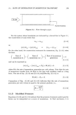
Figure 5.1 Flow through a pipe.
For the system whose boundaries are indicated by a dotted line in Figure 5.1,
the conservation of mass states that
min = mout (5.1-9)
or,
(P(v)A)in = (~(u)A)out +- (zf)in = (zf>out (5.1- 10)
On the other hand, the conservation statement for momentum, Eq. (5.1-3), takes
the form
Rate of Rate of ) + ( Rate of momentum
( momentum in ) - ( momentum out generation ) =O
(5.1-1 1)
and can be expressed as
(m(w>>in - [(h(v))out f FDI f %! (AL) = 0 (5.1-12)
where ?J? is the rate of momentum generation per unit volume. Note that the rate
of momentum transfer from the fluid to the pipe wall manifests itself as a drag
force. The use of Eqs. (5.1-9) and (5.1-10) simplifies Eq. (5.1-12) to
R(AL) - F’ = 0 (5.1-13)
Comparison of Eqs. (5.1-8) and (5.1-13) indicates that the rate of momentum
generation per unit volume is equal to the pressure gradient, i.e.,
(5.1-14)
5.1.3 Modified Pressure
Equations (5.1-6) and (5.1-14) indicate that the presence of pressure and/or gravity
forces can be interpreted as a source of momentum. In fluid mechanics, it is