
Page 198 - Modelling in Transport Phenomena A Conceptual Approach
P. 198
178 CHAPTER 6. STEADY-STATE MACROSCOPIC BALANCES
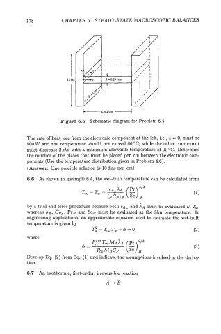
Figure 6.6 Schematic diagram for Problem 6.5.
The rate of heat loss from the electronic component at the left, Le., z = 0, must be
500 W and the temperature should not exceed 80 "C; while the other component
must dissipate 2 kW with a maximum allowable temperature of 90 "C. Determine
the number of the plates that must be placed per cm between the electronic com-
ponents (Use the temperature distribution given in Problem 4.6).
(Answer: One possible solution is 10 fins per cm)
6.6 As shown in Example 6.4, the wet-bulb temperature can be calculated from
(E)
Too - T, = -
2/3
XA
CA,
(PCP)B B
by a trial-and-error procedure because both CA, and j\~ must be evaluated at T,,
whereas PB, Cp,, PrB and SCB must be evaluated at the film temperature. In
engineering applications, an approximate equation used to estimate the wet-bulb
temperature is given by
T: - T,T~ -1- 4 = o (2)
where
Develop Eq. (2) from Eq. (1) and indicate the assumptions involved in the deriv&
tion.
6.7 An exothermic, first-order, irreversible reaction
A-rB