
Page 253 - Modelling in Transport Phenomena A Conceptual Approach
P. 253
PROBLEMS 233
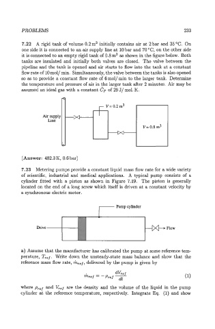
7.22 A rigid tank of volume 0.2m3 initially contains air at 2bar and 35°C. On
one side it is connected to an air supply line at 10 bar and 70 "C, on the other side
it is connected to an empty rigid tank of 0.8 m3 as shown in the figure below. Both
tanks are insulated and initially both valves are closed. The valve between the
pipeline and the tank is opened and air starts to flow into the tank at a constant
flow rate of 10 mol/ min. Simultaneously, the valve between the tanks is also opened
so as to provide a constant flow rate of 6 mol/ min to the larger tank. Determine
the temperature and pressure of air in the larger tank after 2 minutes. Air may be
assumed an ideal gas with a constant 6'p of 29 J/ mol. K.
m
r V= 0.2 rn3
Air supply M
Line
V= 0.8 m3
M
0
(Answer: 482.3 K, 0.6 bar)
7.23 Metering pumps provide a constant liquid mass flow rate for a wide variety
of scientific, industrial and medical applications. A typical pump consists of a
cylinder fitted with a piston as shown in Figure 7.19. The piston is generally
located on the end of a long screw which itself is driven at a constant velocity by
a synchronous electric motor.
I
Pumpcylinder
Drive Flow
a) Assume that the manufacturer has calibrated the pump at some reference tem-
perature, Tref. Write down the unsteady-state mass balance and show that the
reference mass flow rate, mref, delivered by the pump is given by
where pref and V,,f are the density and the volume of the liquid in the pump
cylinder at the reference temperature, respectively. Integrate l3q. (1) and show