
Page 131 -
P. 131
118 M. Wynn et al.
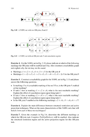
Fig. 3.10 A YAWL net with two OR-joins, B and D
Fig. 3.11 A YAWL net with an OR-join task F and cancelation regions
Exercise 4. For the YAWL net in Fig. 3.10, please indicate at which of the following
markings the OR-joins will be enabled and why. Also construct a reachability graph
and explain why the net may not be sound.
Markings c1 C c2 C c3, c1 C c3 C c5 for the OR-join B
Markings c1 Cc2 Cc3, c1 Cc3 Cc5, c3 Cc4 Cc5, c1 C2c5 for the OR-join D
Exercise 5. Construct a reachability graph for the YAWL net in Fig. 3.11 and please
answer the following questions.
Is marking c5Cc6 a reachable marking of the net? If so, is the OR-join F enabled
at that marking?
If task C fires at marking c1 C c2 C c6, what is the next reachable marking?
Explain the effect of cancelation region upon firing task C.
If task C fires at marking c2 C c6 C c7, what is the next reachable marking?
Explain the effect of cancelation region upon firing task C.
Is the OR-join F enabled at the following markings: c2 C c6, c5 C c6, c6 C c7?
Exercise 6. Explain the main differences between structural restriction and active
projection techniques. What are the main characteristics of the YAWL nets that will
benefit from each of these two techniques?
Exercise 7. Given the example in Fig. 3.6, determine the different markings at
which the OR-join task Complete PickUp/Delivery will be enabled. Also indicate
the structural restriction region and the active projection region for this OR-join
task.