
Page 188 - Modern Control of DC-Based Power Systems
P. 188
152 Modern Control of DC-Based Power Systems
R fn L fn I Ln
d ·E n C fn
n
I = P /V
V C eq R L CPL CPL
R fm L fm I Lm
d ·E m C fm
m
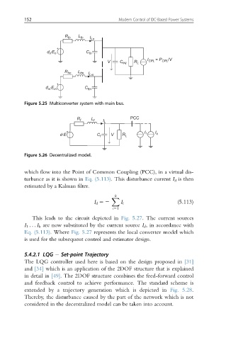
Figure 5.25 Multiconverter system with main bus.
R f L f I L PCC
d·E C f V R L I 1 I k
Figure 5.26 Decentralized model.
which flow into the Point of Common Coupling (PCC), in a virtual dis-
turbance as it is shown in Eq. (5.113). This disturbance current I d is then
estimated by a Kalman filter.
k
X
I d 52 I i (5.113)
i51
This leads to the circuit depicted in Fig. 5.27. The current sources
I 1 .. . I k are now substituted by the current source I d , in accordance with
Eq. (5.113). Where Fig. 5.27 represents the local converter model which
is used for the subsequent control and estimator design.
5.4.2.1 LQG Set-point Trajectory
The LQG controller used here is based on the design proposed in [31]
and [34] which is an application of the 2DOF structure that is explained
in detail in [49]. The 2DOF structure combines the feed-forward control
and feedback control to achieve performance. The standard scheme is
extended by a trajectory generation which is depicted in Fig. 5.28.
Thereby, the disturbance caused by the part of the network which is not
considered in the decentralized model can be taken into account.