
Page 41 - Modern Optical Engineering The Design of Optical Systems
P. 41
24 Chapter Two
Figure 2.2 A ray directed toward
the first nodal point (N 1 ) of an
optical system emerges from the
system without angular deviation
and appears to come from the
second nodal point (N 2 ).
The power of a lens or an optical system is the reciprocal of its effec-
tive focal length; power is usually symbolized by the Greek letter phi ( ).
If the focal length is given in meters, the power (in reciprocal meters)
is measured in diopters. The dimension of power is reciprocal distance,
1
e.g., in , mm , cm , etc.
1
1
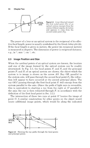
2.3 Image Position and Size
When the cardinal points of an optical system are known, the location
and size of the image formed by the optical system can be readily
determined. In Fig. 2.3, the focal points F 1 and F 2 and the principal
points P 1 and P 2 of an optical system are shown; the object which the
system is to image is shown as the arrow AO. Ray OB, parallel to
the system axis, will pass through the second focal point F 2 ; the refrac-
tion will appear to have occurred at the second principal plane. The
ray OF 1 C passing through the first focal point F 1 will emerge from the
system parallel to the axis. (Since the path of light rays is reversible,
this is equivalent to starting a ray from the right at O′ parallel to
the axis; the ray is then refracted through F 1 in accordance with the
definition of the first focal point in Sec. 2.2.)
The intersection of these two rays at point O′ locates the image of
point O. A similar construction for other points on the object would
locate additional image points, which would lie along the indicated
Figure 2.3 Showing the ray paths through the focal points
and principal points.